Initialization
In order for us to create a functional simulation of the functionalities of ZetaBot we need to have a functional virtual replica of the robot as well as a simulated environment that can be interactive.
Our example used Isaac Sim application provided by the NVIDIA OmniVerse. With Isaac Sim we are able to create, edit, and simulate objects and environments.
ZetaBank provides a premade environment with the zetabot figure already created and are stored in a usd file format.
For more information on USD file format: Universal Scene Description
We may check these object individually by accessing the Stage window.
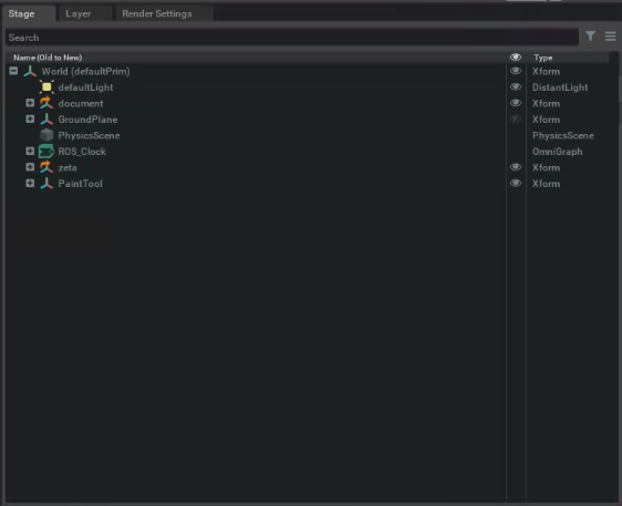
For a proper simulation to take place there must be a GroundPlane and a PhysicsScene. These variables are already set within our environment, and can be found in the Stage window.
They can also be created using the Create->Physics dropdown window.
You may also change the lighting of the environment by double clicking on the defaultLight variable in the Stage menu. This action will prompt the Property window below the Stage window.
The robot is set to be not bound to the ground and the wheels attached to the motors are set to have a velocity to simulate correct physics.
Robot Tuning
The premade virtual zetabot may be tuned to fit the users needs. There are three main tuning that needs to be done for the robot to function correctly.
Frictional Properties
Frictional Properties dictates the level of surface friction on either the robot or the surrounding environment. If the robot wheels or the ground is too slippery, the movement of the robot will be wrong and further simulations such as navigation will yield wrong results.
You may change the friction level by accessing the zeta variable in the Stage window and locating WheelPhysicsMaterial in zeta (robot) variable. The default setting is 1.
Physical Properties
If the robot does not have explicit mass or inertial values, the physics engine will assume them as geometric mesh. In order to set the mass for an object, it can be done by Physics -> Mass objection from the dropdown menu.
Since our robot is made up of multiple different parts, the mass for each of the parts were given separately. You may check these within the Property window.
Joint Property
The Joint Property allows for joint stiffness and dampening settings.
When the joints are set to high stiffness, the movements are much more sharper and faster.
When the joints are set to high damping, it smooths the movement of the robot but also makes it much more slower.
For our application, we mush have high stiffness and low damping for positional drive.
Other Properties
You may also check our all the other properties such as visual or shader to see how the virtual zetabot was made.
Robot Driving
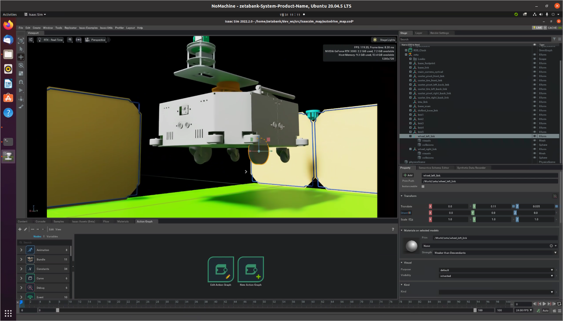
Within the zeta variable in the Stage window, we can see a variable named ActionGraph. This variable reprsents the ROS bridges in forms of OmniGraph nodes.
For more information on ActionGraph: Action Graph
To access the ActionGraph:
Open the Action Graph window (Window -> Visual Scripting -> Action Graph)
Press Edit Action Graph (Since we already have an action graph we do not need to create a new one)
The Action Graph allows the Virtual robot to communicate with different nodes. This allows for user inputs to navgiations and so on.
To check the ROS connection, and move the Robot:
Play the simulation.
Open a new terminal and execute:
rostopic listThis allows for all the associated rostopics presents. Verify that
/cmd_vel,/rosoutand/rosout_aggare present.Open another new terminal and publish a twist message to /cmd_vel topic which controls the robot:
rostopic pub /cmd_vel geometry_msgs/Twist '{linear: {x: 0.2, y: 0.0, z: 0.0}, angular: {x: 0.0,y: 0.0,z: 0.0}}'